FPGA ZCU104: Getting Started & Flash Programming Guide
This README provides step-by-step instructions for setting up, debugging, and programming the ZCU104 FPGA board. It assumes that you have already generated the bitstream and installed the necessary tools. Please refer to the following before proceeding:
Hardware Connection Steps
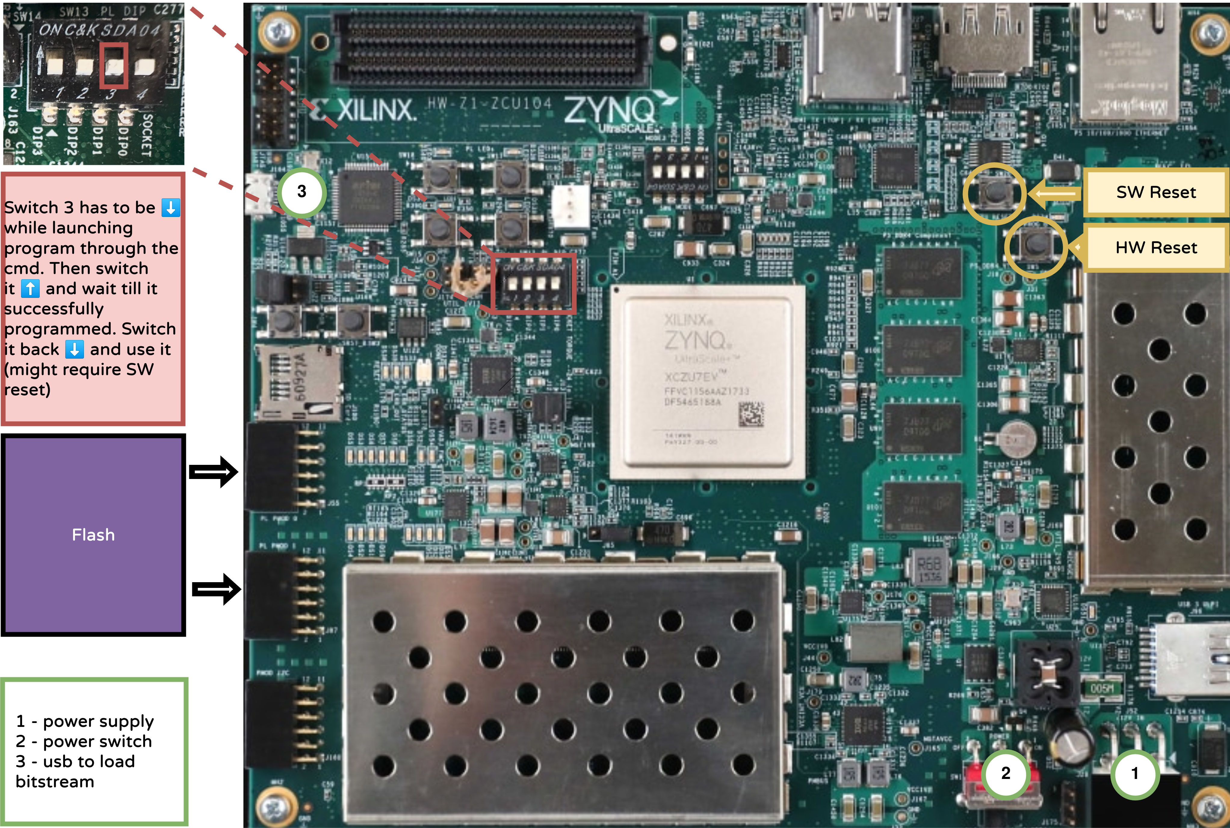
Power Up the Board
Connect the power supply as shown in the schematics (1).
Turn on the board using the power switch (2).
Connect USB
Use a USB cable (3) to connect your development machine to the board.
Ensure Vivado Board Files Are Installed
Vivado must be able to recognize the ZCU104 board. Ensure the board files are placed in the following directory:
<Vivado_Install_Dir>/data/boards/board_files
You can obtain the board files either from:
Connect the Flash
Connect the external flash module to the board as illustrated in the schematics above.
Programming the Board
The steps for programming the board are the same as for pynq board, the only modification you have to do is to change the TARGET.
Compile the App and program the flash Refer to the Compile the Apps Documentation
make app LINKER=flash_load TARGET=zcu104 PROJECT=hello_world
Program the Flash Programming of the Flash is done in few steps, refer to the figure for the assistance:
Launch the programming with all the switches off.
make flash-progSet the third switch on the board up.
When the device is correctly programmed, the ICEProg tool will show a non-zero address.
Set the switch back down to boot the software from flash.
If needed, restart the application, press the reset switch (highlighted in yellow on the board).
make flash-prog(OPTIONAL: used for DEBUG) Open a Serial Connection (To see printf in the terminal)
You can connect to the board’s serial console using
picocom. Run the following command:
picocom -b 9600 -r -l --imap lfcrlf /dev/serial/by-id/usb-FTDI_Quad_RS232-HS-if02-port0
Notes
Refer to the schematics diagram included in the repo for switch and connection references.
Always make sure the bitstream and Vivado configuration match your hardware revision.